

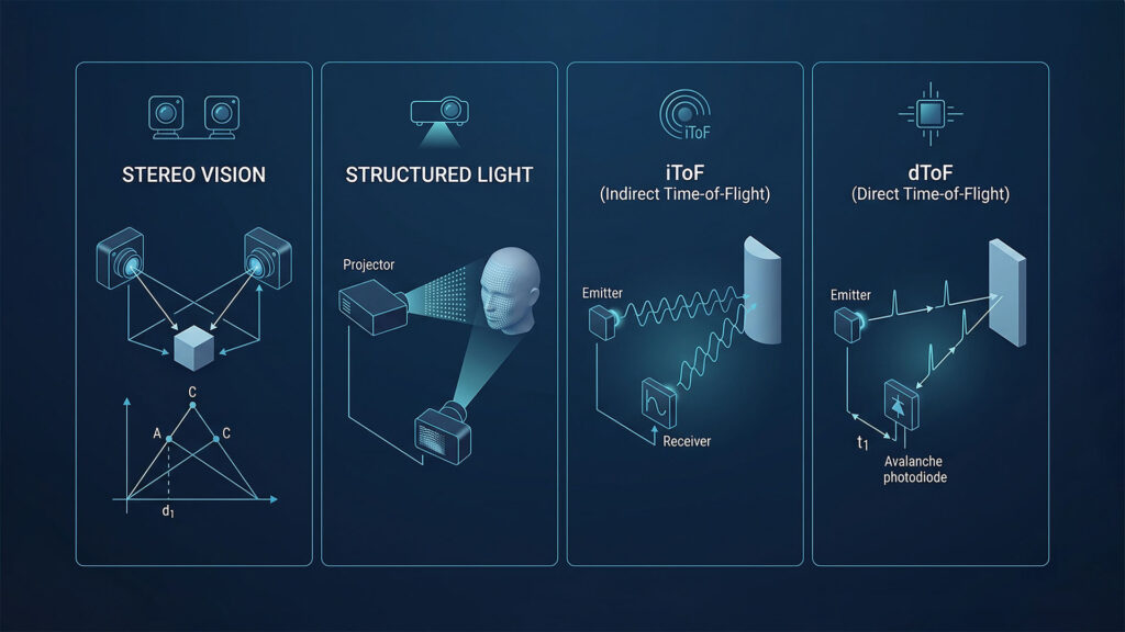
To help users make informed decisions when choosing among various 3D vision hardware solutions, we have compiled this document for your reference, providing a general analysis of the principles, advantages, disadvantages, and application scenarios of the four mainstream 3D vision sensors: Stereo Vision, Structured Light, iToF, and dToF.
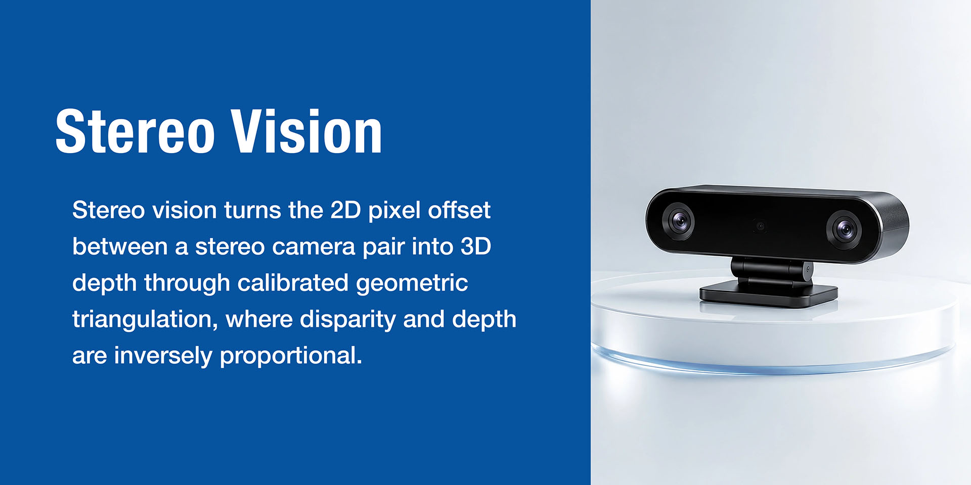
A passive ranging technology that mimics the human eye’s disparity principle. It is divided into passive stereo and active stereo.
Stereo depth reconstruction uses triangulation to calculate the distance from the object being measured to the camera. When two cameras observe the same object, the positional difference of the object in the two images is called disparity. The closer the object is to the camera, the larger the disparity; the farther away, the smaller the disparity.
Given the known relative positional relationship (e.g., the distance between the two cameras), the distance can be calculated using similar triangle principles.
| Aspect | Passive Stereo | Active Stereo |
|---|---|---|
| Principle | Relies solely on natural texture from ambient light; calculates disparity through image matching | Adds an infrared laser projector (dot matrix/speckle/line) to actively project texture, enhancing matching in low-texture areas |
| Advantages | Low cost, low power consumption, no active light interference, multiple devices can work simultaneously | Usable in low-light or textureless scenes; more stable performance than passive stereo |
| Disadvantages | Essentially unusable on low-texture surfaces (white walls) or in low-light conditions | Projection patterns interfere with each other when multiple devices work together, causing matching failures; pattern is easily overwhelmed by strong outdoor sunlight, degrading depth performance |
| Typical Representatives | Stereolabs ZED series, Senseno | RealSense D400 series, Luxonis OAK series, Orbbec Gemini series |
Active stereo is an enhanced version of passive stereo. The infrared fill light solves the pain points of low-light and low-texture conditions. However, it does not fundamentally improve issues such as long-range accuracy or strong light interference. Active stereo still suffers from the inverse-square degradation of accuracy inherent to triangulation methods. Furthermore, when multiple active stereo devices operate simultaneously, projected patterns interfere with each other, leading to matching failures.
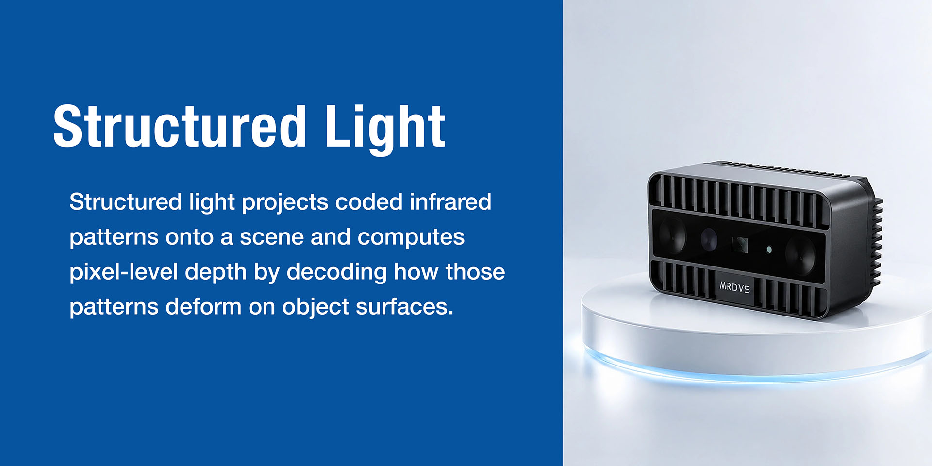
An active triangulation technique that actively projects a coded pattern and directly solves for depth through pattern deformation.
Structured light is an active triangulation measurement technique, belonging to the same broader category as active stereo vision.
The working method is as follows: an infrared laser projector casts a structured light pattern containing coded information (such as stripes, grids, or pseudo-random dot arrays) onto the object being observed. These patterns deform (e.g., stripes bend, dots shift) according to the object’s geometry and distance. An infrared camera captures these deformed patterns, and the system decodes the degree of deformation to directly calculate the depth information for each pixel.
| Aspect | Active Stereo | Structured Light |
|---|---|---|
| Depth Calculation | Calculates disparity by matching corresponding points in left and right images, relying on correspondence between images | Directly obtains depth by decoding pattern deformation; each projected feature point carries its own “identity tag” and does not rely on stereo matching |
Consumer Apple Face ID module, Orbbec Astra series (mainly used for close-range face recognition, 3D modeling, etc.)
Industrial Photoneo MotionCam-3D series, Mech-Mind Mech-Eye series, Zivid products
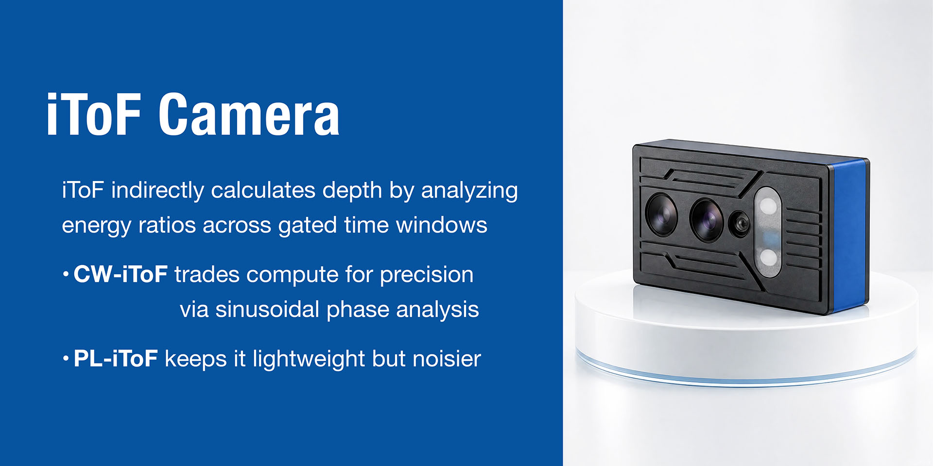
A ranging technique that indirectly calculates flight time through phase difference.
iToF (indirect Time-of-Flight) collects energy values at different time windows, analyzes the proportion between these values, and indirectly measures the time difference between the transmitted and received signals. It is mainly divided into two modulation methods:
CW-iToF (Continuous Wave): Uses sinusoidal wave modulation. The phase shift between the received and transmitted sinusoidal waves is proportional to the object’s distance. Accuracy is limited by random noise and quantization noise. To improve accuracy, high-power, short-integration-time sampling combined with high modulation frequency is typically used.
PL-iToF (Pulse Modulation): Emits light pulses with amplitude and time information. Uses dual-sampling techniques to improve accuracy. The calculation is simpler and has lower computational load, but accuracy is weaker than CW-iToF, and it is more sensitive to background noise.
iToF chip manufacturers: Sony, Infineon, PMD.
Module manufacturers: Lucid Helios2 series, SICK Visionary-T Mini, MRDVS M series, IFM 3D cameras.
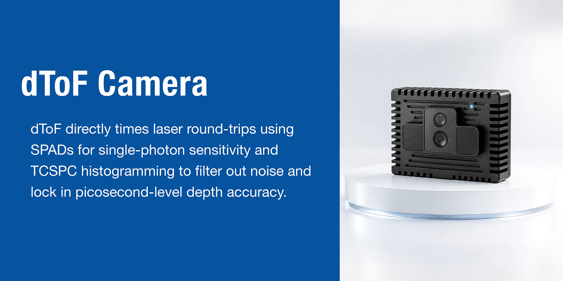
The ultimate ranging technique that directly measures the round-trip time of photons.
dToF (direct Time-of-Flight) technology directly measures the time difference between emitting and receiving a light pulse. Due to laser safety limits and consumer product power constraints, the pulse energy emitted by ToF cameras is limited. By the time the light returns to the receiver, the energy density has decreased by more than a trillion times. Ambient light acts as noise, severely interfering with signal detection.
Therefore, dToF requires extremely sensitive photodetectors: Single-Photon Avalanche Diodes (SPADs). When a SPAD is in operation, it is biased with a high reverse voltage. When a photon is absorbed and converted into a free electron, the strong internal electric field accelerates this electron, which collides to generate more carriers, creating a geometrically amplified avalanche effect, thereby outputting a large current pulse and achieving single-photon detection.
dToF uses the Time-Correlated Single-Photon Counting (TCSPC) method to achieve picosecond-level time precision. The system repeats the emission-detection of the same pulse signal thousands to hundreds of thousands of times, obtains a statistical distribution histogram from each detection, reconstructs the curve of light pulse energy over time, and thus derives the precise flight time.
Consumer/Mobile Apple LiDAR (iPad Pro/iPhone Pro series).
Industrial RoboSense E1/E1R, MRDVS S series.

